Coal based power plant | PPT SlideShare
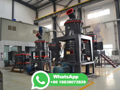
A thermal power station is a power plant in which the prime mover is steam driven. Water when heated turns into steam which drives a steam turbine. After passing through the turbine, the steam is condensed in a condenser and recycled to where it was heated. [Rankine cycle] Coal is used as a fuel to heat water in a coal based thermal power plant.
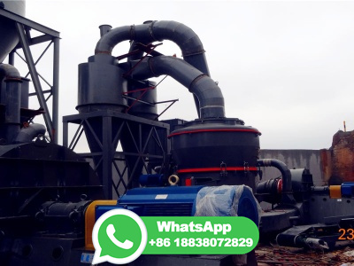
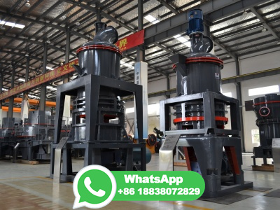
![Schematic diagram of a coalfired steam power plant [11]. ResearchGate](/sf6q94p/293.jpg)


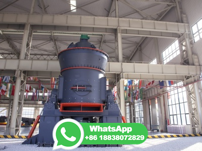
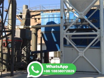
![Gas Turbine Power Plant: Diagram, Working Types [PDF]](/sf6q94p/346.jpg)